|
|
|
|
|
|
Anders Dinsen
Administrator
YaBB God

Posts: 3240

Email
|
 |
« Reply #78 on: March 11, 2010, 09:17:30 am » |
|
Hi Andy I really enjoy reading your progress reports. Thanks also for sharing the funnier experiences! We've all tried that, so I don't feel bad laughing over the missed connection of the pressure gauge  About the mesh, on N/A engines, mesh is usually not recommended as it disturbs the airflow quite a bit. The mesh itself of course reduces the area through which the air flows, but more important it also creates quite a bit of turbulence, reducing airspeed. Mesh used to be popular on competition cars in front of carburettors instead of filters, but it's not a good idea - a proper filter is always better if you don't dare running without. I understand why you want it, but you're after power... I'd remove it and accept the risk. Besides, nuts don't just fall off if tightened correctly - and especially not when done with loctite Keep up the good work and good luck with mr. Hill /Anders Just noticed one other thing: You don't need the heat insulating carb bases with your new setup. A simple paper gasket will do. |
|
|
|
« Last Edit: March 11, 2010, 09:22:21 am by Anders Dinsen »
|
 Logged
|
1982 Talbot Matra Murena 2.2 prep 142 (under restoration)
Used to own:
2001 Renault Matra Grand Espace "The Race" V6 24v
1997 Renault Matra Espace 2.0 8V
1987 Renault Matra Espace J11 2.2
|
|
|
|
|
|
|
|
|
andyowl
Sr. Member

Posts: 456
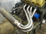
New exhaust "straight through" - good sound!
Email
|
|
« Reply #82 on: March 20, 2010, 09:16:38 am » |
|
I road tested Baggy Joe with the supercharger several times in the last week. The power increase feels HUGE! It was at least an hour before my knees stopped vibrating after the last run with the relief Valve opening pressure increased to about 0.8 bar. The car just flies and the "Blower Howl" makes my spine tingle. There are too many things happening at the same time to register them all. Wow!
There have been some problems however. During one of the first runs I could hear the Relief Valve ("RLV") opening with about 0.2 bar on the boost pressure gauge. I screwed down the spring a bit and the maximum boost pressure rose to 0.5bar. Feeling brave I gave it a last adjustment to the limit of the thread on the screw. 0.7bar was seen briefly but it started to drop back again. I looked at the neoprene valve seal and saw that it was dissolving! Despite the "material compatibility charts", which suggest that Neoprene is OK with unleaded gasoline, my neoprene foam gasket doesn't agree! As a short term fix I have made a very thin (0.05mm) brass disc to go between the foam and the manifold body. I hope this will reduce the contact between the gasoline and the rubber. I have not driven this solution yet.
At long last I have wired up the "Low Oil Pressure Warning Light". I had forgotten that I had done most of the work already and the hook up was very quick. The light itself is a 25mm lens where the cigar lighter normally sits. I can see it through the lower half of the steering wheel. It should be very visible if it lights up during an event. The oil pressure gauge also works but that requires "looking at" whereas the bright alarm light should attract attention. I hope it never needs to operate. The big worry is that the Shorrock blower consumes engine oil and it may not take long before the oil needs filling up again. In the heat of competition I may forget. The warning light is the last chance! What I really need is an oil LEVEL warning system.
Oil leaks in the nylon pipes feeding the oil pressure warning light switch and the blower lube oil line have also been a problem. I have used "Legris" pneumatic push-in fittings for over 30 years and found them very good if installed correctly. If air leaks out nobody really cares or noticed. Oil dripping out is a very different matter and easy to see especially if it results in smoke (Oh my God, its on fire!) or "What is that puddle on the floor" or worse "If your car leaks oil on the race track you will be banned and hated by everyone else". Not a good scenario! So I think I will have to re-pipe the system using compression fittings and/or use copper pipe. I checked in the RS catalogue last night and only Enots/Norgren compression fittings are listed. I loathed these fittings when I was a site engineer in the '60's and I don't feel much happier about them now. Apart from expensive USA Oil Industry compression fittings, anyone got any ideas on better systems? Wade and Simplifix were two competing brands 20 years ago but I haven't checked recently. Using copper would seem to be a good idea but I worry about fatigue cracking. Maybe I should be using oil-resistant rubber pipes?
Finally, I have now cut two large holes in the engine cover (yesterday) for the top of the SU carb vacuum dome and for the carb air inlet filter. Not the prettiest jigsaw job I ever did but the first AutoSolo event is tomorrow and the scrutineers will want an engine cover in place, even with two holes in it! Today is time to stick the fabric back on the engine cover, re-fit the interior trim (door cards and original twin passenger seat) as they are also required. Adding weight is not what I want to do!
Wish us luck.
The event (Sunday March 21st) is held at the Montgomery Lines parade ground, off Alison Road in Aldershot, Hampshire. Entry is free to spectators. All welcome. Come to the motorhome and stay for coffee! We should be there around 0830. Action starts after the driver's briefing at 10am. You may get press-ganged into helping to marshal!
Andy
|
|
|
|
|
Logged
|
Back in business for fun!
|
|
|
Spyros
Sr. Member
Posts: 325
I'm a real donkey!
WWW
Email
|
|
« Reply #83 on: March 21, 2010, 10:00:54 am » |
|
Hi Andy, You are progressing so quickly ! I'm not sure to understand how you made the low pressure light work ? Don't we have, by default, the sensor, however unwired ? If I understand well, you needed an oil supply for the blower. Did you took it from the oil pressure sensor or elsewere ? Like I'm doing here ?  Regards |
|
|
|
|
Logged
|
|
|
|
|
|
andyowl
Sr. Member
Posts: 456
New exhaust "straight through" - good sound!
Email
|
|
« Reply #85 on: April 02, 2010, 11:35:06 am » |
|
"Rolling Road" testing....
Yesterday we visited TCS Performance Ltd., near Bishop's Stortford, who provided the rolling road on which Baggy Joe was tested last August at the Practical Performance Car "RetroRide" event at Haynes Motor Museum.
[Just in case someone is not aware of what a "Rolling Road" does here goes. The driving wheels of the car rest on two large rollers which are connected to generators. The driver runs the engine and accelerates the rollers through 1st, 2nd, 3rd and 4th gears. He then lets the engine slow down to around 1,500rpm and opens the throttle fully. The generators provide the load on the engine and the computer records the electricity being produced and converts that to "Horse Power". A graph is plotted showing the Horse Power at the wheels, calculates the HP at the flywheel i.e. excluding the losses of the transmission and tyres, and several other things. Air/Fuel ratio is important to a blower system as having a mixture with too much air can cause the pistons to overheat and melt! He also records the inlet manifold pressure (the Blower Pressure) and several other things if you wish.]
In August last year the maximum Horse Power recorded was 88.6HP. (I need to convert this Imperial figure to metric! Do you prefer kW or something else?). We now know that a 1592cc Solara engine had been fitted by a previous owner and that it is in reasonably good condition.
Having now fitted the supercharger and got it running reasonably well, I felt that we should have some proper testing done to try to maximise the power and check those things that are difficult to do while the car is stationary such as how the mixture varies throughout the rev range and check the ignition system working with the engine under high speed/high load conditions. All these can be done on the rolling road with the car stationary.
The car was reversed onto the rollers and strapped down very tight to prevent it coming off and running down the road! Sensors were added including a "Lambda" sensor to measure the Air/Fuel ratio and a thermocouple to measure the inlet air temperature. My blower pressure gauge was disconnected and the manifold pressure sensor connected in its place. There must also have been a connection to the ignition system (to monitor the engine speed) but I don't remember seeing it.
The photoghraph of the computer screen below showed some of the many graphs the computer produced. I will scan the paper graphs he provided shortly but the main interesting figures are shown. At the top right hand corner are the maximum Horse Powers recorded with 98.2HP being the HP as first tested and 112.7Hp the best we achieved after changing settings. So we gained 14.5HP just for changing the mixture, changing the ignition timing and closing the spark plug gaps down to 0.65mm! He charged £60 (about Euro65). So compared with August 2009 we have increased the power from 88.6 to 112.7 a gain of 24.1 HP or 27.3%.
I confess this is not quite as much as I had hoped for as the conventional wisdom suggests that 40% increase should be achievable. Still it feels a lot better and I would be very pleased to improve the driver's performance by 27% in four months!
More pictures and analysis to follow later.
Have a nice Easter!
Best wishes, Andy Owler
|
|
|
|
|
Logged
|
Back in business for fun!
|
|
|
|
|
|
|
|
|
|
|

 Author
